What is Pinger?
Pinger is device which:
- monitors Internet connectivity over WiFi by pinging a website;
- keeps a log of when connectivity is lost and regained;
- resets an attached router or modem through 1 “wet” (electrically powered) connection and 1 “dry” electrically isolated connection; and
- is fully configurable via a web interface.
Besides being a useful device the software includes code which:
- gets Internet time and displays it in human readable form (i.e. 2016/07/9 11:32:21);
- shows basic use of HTML and a web interface (but my HTML code is awful); and
- shows how to use the SPIFFS file system.
Background & Ancient History
Pinger is a project I started a number of years ago when I had unreliable wireless Internet based on 3G wireless. It not only cost a fortune ($400/month for 30GB) it was slow and a few times a week I’d have to reset my router. This was a pain in the butt, but something I could do. Unfortunately it is not something I could do while I was away from my home.
I started working on a solution with an Arduino and a Ethernet shield but, but I got new Internet service before I finished up so the need went away. A little while after that my friend Gabriel was complaining he lost Internet service regularly but his ISP refused to believe it. I figured a “logger” might help him out but his ISP replaced his modem and the problem went away.
One of the projects I have been working on for some time now is a control system for my geothermal hydronic heating system.The way the system is set up I can in principal control the temperature in each room individually but the control system I got when I installed the hydronics was too primitive to do that. As a result I have 3 zones, but, since I have a large house that means in the winter some rooms are too hot due to passive solar heating and some are too cold. I needed a system which could measure the temperature in each room and control the heat that way.
The problem was wiring 12 thermostats and 15 control valves would be a nightmare.
I recently started using the ESP8266 which is a complete 2.4GHz WiFi solution as well as a programmable microprocessor. I immediately realized I could use the ESP as a wireless thermometer (think Nest without the hype) and as a wireless control valve controller.
I settled on using the WeMos D1 mini because they as cheap – $4 on AliExpress – and as close to the ESP8266 as you can get. I originally chose a Beaglebone to use as the hub but when the Raspberry Pi 3 came out I decided it was cheaper and good enough.
As I started writing my code I realized I had to learn a lot about programming the ESP8266. I noticed a thread on reddit which discussed a commercial product similar to my Pinger project and I figured I would learn most of what I needed by completing Pinger on an ESP8266.
Pinger Hardware Design
Even though the software is fully written I’m going to start off with the hardware design.
Why Did You Use Through Hole Components?
I was an early adopter of Surface Mount Technology (SMT) when I was a design engineer. There are many reasons to use SMT:
- SMT parts are often cheaper and more available;
- SMT parts are smaller and therefore you can use a smaller (and therefore cheaper) PCB;
- you can install SMT parts on both sides of the board; and
- it is much cheaper make an SMT product on a modern assembly line.
However SMT is not ideal for hobbyists:
- SMT ICs are hard to place by hand without damaging the leads;
- you either need a PCB to make your project or you have to buy adapter boards if you want to build on a perfboard;
- it is hard to solder the board properly with a soldering iron;
- you have to know what you are doing to solder using paste/reflow;
- it is hard to spot or repair bad solder joints; and
- it can be very hard to use a multimeter and other basic test instruments on SMT components.
So, just to be clear I am a big fan of SMT and I have a reflow oven and all the stuff I need to do SMT, including a large inventory of parts and adapters. However most people don’t so if I am going to publish a design I’ll make an effort to use through hole parts as much as possible.
Why Kicad and Arduino-Eclipse
The schematics and boards were designed in Kicad 4. Kicad isn’t perfect but it is free and very capable. I used Eagle for a while but started running into limits with their free license. I can afford to license Eagle but you never know when the license terms are going to change. Besides how would you open the files?
Because the software consists of several modules and is a few thousand lines long (I do use comments) I switched from the Arduino development platform to Arduino-Eclipse V3. Eclipse is not a perfect IDE but it is a huge step up in quality from the Arduino IDE. I may take the tine to verify my source compiles with Arduino once I’ve finalized the code since most hobbyists are more comfortable with Arduino.
Suppliers
I mostly use Digikey as my parts supplier. When I was a practicing engineer you almost had to beg suppliers to sell you small quantities of parts and it was often easier to beg for free samples from applications engineers than actually buy the things. Besides gouging you on price you might have to wait 16 weeks or more for the parts.
In contrast, Digikey is happy to sell to anybody with a credit card. They have a vast inventory and you get the same price breaks as anybody else. Canada is a wasteland for electronics but if I place my order with Digikey before about 3PM I will have my parts in hand by 5PM the next day. They are awesome and no they aren’t paying me to say that.
I ordered my PCBs from Seeed Fusion and should get them in about two weeks because I paid for express delivery. I’ve used Seeed in the past and their boards are good value for money.
Design Documentation
As usual, I ordered all the parts from Digikey before submitting the PCB for manufacturing in order to to make sure all the packages were what I thought they were. The way I do that is I print out the top layer of the board at 1:1 and plug the parts into the paper. In this case I discovered I had put the two relays too close to each other and that is a lot easier to correct in the CAD file than the actual PCB.
Once I get the boards back I will assemble one and verify the hardware design. Chances are the schematic is correct but I have been known to screw up the layout. As soon as I verify the layout I’ll publish the full KiCad files.
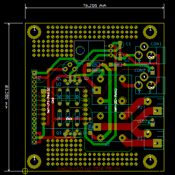
Until then this PingerSchematic is a link to a PDF of the schematic. The picture above is the PCB layout and this PingerReference contains a complete parts list including ordering information from Digikey as well as an explanation as to why I selected those components.
Print out both files and study them before building anything. You should be able to assemble the project on a standard perfboardO except for the relays, barrel connectors, and wire to board connectors where you might have to drill extra or oversized holes. Drill the holes before you start installing parts. Try and get a perfboard at least 4″x4″ with plated through holes and “pad per hole”.
Note that the “dry” relay can handle AC including dangerous voltages. I am not responsible for any use of this design.
What’s Next?
I should get the boards in a couple weeks. After I prove the layout and publish the Kicad files I will have another look at the software and ensure the I/O assignments, etc., are correct for the PCB. Then I will publish the full software source listing as well as a binary file you can simply program into your ESP8266-12 breakout board. I have not figured out the procedure for programming from a binary yet but I will publish that as well.
Please note that this document and related materials are released under the Creative Commons Attribution-NonCommercial 2.0 license. Please see https://creativecommons.org/licenses/by-nc/2.0/ca/ for details/limitations.
